

Introduction
In this article, I will explain the concept of an IoT based smart trash can. It will automatically open when we take waste to it; and when it is full, a light will come on automatically
Hardware Parts
- Arduino Uno
- UltraSonic Sensor-2
- Servo motor
- LED
- Buzzer
- Bread Board
- HookUp wires.
Software Parts
- Arduino IDE.
Parts Explanation
UltraSonic Sensor
- It is used to produce a high-frequency sound effect.
- It can measure the signal from the sender to the receiver.
- The echo is to be determined from the object.
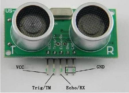
Figure1 UltraSonic Sensor.
- It is small and cost-effective.
- It is used for small robotics and radio controls.
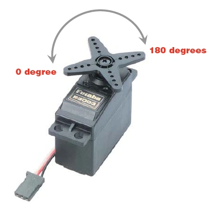
Figure 2 ServoMotor
- A buzzer is a sound maker which can alert you to a problem
- Then in the buzzer which can have the gnd and vcc
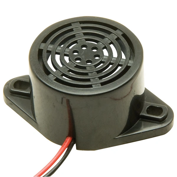
Figure 2 Buzzer
Step 1 UltraSonic Sensor-1 to Arduino
- Connect the Vcc of the Ultrasonic Sensor to the 5v of the Arduino Uno.
- Connect the Gnd of the Ultrasonic Sensor to the Gnd of the Arduino Uno.
- Connect the First Trigger of the Ultrasonic Sensor to the 5 of the digital Input in the Arduino Uno.
- Connect the First Echo of the Ultrasonic Sensor to the 4 of the digital Input in the Arduino Uno.
Step 2 UltraSonic Sensor-2 to Arduino
- Connect the Vcc of the Ultrasonic Sensor to the 5v of the Arduino Uno.
- Connect the Gnd of the Ultrasonic Sensor to the Gnd of the Arduino Uno.
- Connect the First Trigger of the Ultrasonic Sensor to the 7 of the digital Input in the Arduino Uno.
- Connect the First Echo of the Ultrasonic Sensor to the 6 of the digital Input in the Arduino Uno.
Step 3 Servo Motor To Arduino
- Connect the Vcc of the ServoMotor to the 5v of the Arduino Uno and also connect the vcc in the 8th pin of the Arduino.
- Connect the Gnd of the ServoMotor to the Gnd of the Arduino Uno.
Step 4 Buzzer To Arduino
- Connect the Vin of the buzzer to the 2 of the Arduino Uno.
- Connect the Gnd of the buzzer to the Gnd of the Arduino Uno.
Step 5 Led To Arduino
- Connect the Led1 to Negative pin to the Arduino Uno
- Connect the Led1 to positive pin 8 to the Arduino Uno
- Connect the Led2 to Negative pin to the Arduino Uno
- Connect the Led2 to positive pin 9 to the Arduino Uno
- Connect the Led3 to Negative pin to the Arduino Uno
- Connect the Led3 to positive pin 10 to the Arduino Uno
- Connect the Led4 to Negative pin to the Arduino Uno
- Connect the Led4 to positive pin 11 to the Arduino Uno
Figure Of the Connection
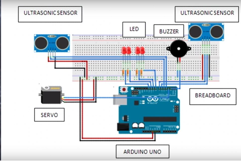
Figure 4 Connection
- #define pingTrig2 7
- #define pingEcho2 6
- #define pingTrig 5
- #define pingEcho4
- #define buzzer 2
- #include < Servo.h >
- Servo myservo()
- void setup() {
- Serial.begin(9600);
- PinMode[PingTrig2, OUTPUT];
- PinMode[PingEcho2, OUTPUT];
- PinMode(8, OUTPUT);
- PinMode(9, OUTPUT);
- PinMode(10, OUTPUT);
- PinMode(11, OUTPUT);
- PinMode(Buzzer, OUTPUT);
- PinMode(pingTrig, OUTPUT);
- PinMode(pingEcho, OUTPUT);
- myservo, attach(3);
- }
- Void Loop() {
- lond duration2 distance2;
- digitalWrite(pingTrig2.LOW);
- delay Microsecconds(2);
- digitalWrite(pingTrig2.HIGH);
- delay Microsecconds(10);
- digitalWrite(pingTrig2.LOW);
- digitalWrite(buzzer, LOW);
- duration2 = PulseIn(pingEcho2, HIGH);
- distance2 = duration 2 / 20 / 2;
- if (distance 2 > 15) {
- open close();
- } else {
- mysowo,
- write(0)
- lighting();
- digitalwrite(buzzer, low)
- }
- void openclose() {
- long during, inches, cn;
- digitalwrite(pingTrig, LOW);
- delay Microseconds(02);
- digitalwrite(pingTrig, HIGH);
- delay Microseconds(10);
- digitalwrite(pingTrig, Low);
- duration = pulseIn(pingEcho, High);
- cn = duration / 29 / 2;
- if (cn < 10) {
- myservo.write(50);
- delay(100);
- } else {
- myservo.write(0);
- }
- delay(1000);
- void lighting() {
- digitalWrite(buzzer, HIGH);
- digitalWrite(8, HIGH);
- digitalWrite(9, HIGH);
- delay(300);
- digitalWrite(8, LOW);
- digitalWrite(9, LOW);
- digitalWrite(10, High);
- digitalWrite(11, High);
- delay(300);
- digitalWrite(10, Low);
- digitalWrite(11, Low);
- delay(300);
- }
Explanation
- It will sense when we want to put waste in the can and when the can is full a light will come on.
Output
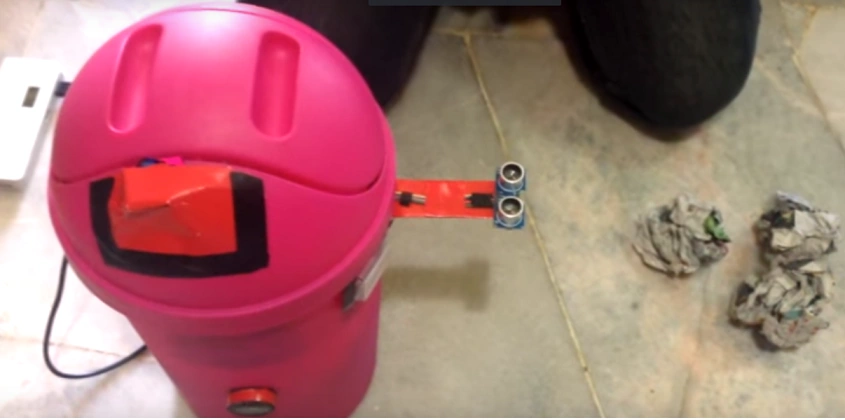
Figure 5 Output 1
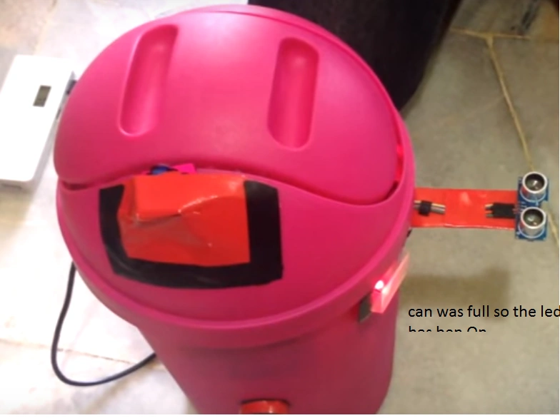
Figure 6 Output 2
sis broPosted Mar 14, 2019, 5:50 PM
Sir can i see your video please. :(
suketu patelPosted Aug 25, 2018, 12:57 PM
This code r not uploading ,,, please help me , send me a new code
Hadshana KamalanathanPosted Jul 21, 2018, 8:03 PM
Nice one..
shram sarkawtPosted May 3, 2018, 3:28 PM
This codes are wrong please sent us the arduino file
Shekhar PanwarPosted Feb 13, 2017, 1:55 AM
Great article about the smart can Sr Karthiga
RajaPosted Feb 12, 2017, 11:33 PM
Nice article thanks for share....
Sr KarthigaPosted Feb 12, 2017, 1:04 AM
Thank you sir but i did not use the battery in this smart can i use direct current from the Ac current...
Vignesh ManiPosted Feb 11, 2017, 4:59 PM
Good one. Thanks for sharing.
Anu VPosted Feb 11, 2017, 5:23 AM
Nice article thanks for sharing..
Mahesh ChandPosted Feb 10, 2017, 8:27 PM
This is very cool. What I hate about smart cans is, it doesn't know when their battery is dead. I think it will be cool to figure out battery life left for a can and warn me.