Transmission Media
In data transmission system, transmission medium is used between transmitter and receiver. Transmission media can be classified as guided and unguided. In both cases, communication is in the form of electromagnetic waves. With guided media, the waves are guided along a solid medium, such as copper twisted pair, copper coaxial cable and optical fiber. The atmosphere and outer space are examples of unguided media that provide a means of transmitting electromagnetic signals but do not guide them, this form of transmission is usually referred as wireless transmission.
Guided Transmission Media
In guided transmission media, transmission depend on data rate, bandwidth, distance, medium is point-to-point or multipoint in LAN.
| Transmission Medium |
Total Data Rate |
Bandwidth |
Repeater Spacing |
| Twisted Pair |
4 Mbps |
3 MHz |
2 to 10km |
| Coaxial cable |
500 Mbps |
350 MHz |
1 to 10km |
| Optical fiber |
2 Gbps |
2 GHz |
10 to 100km |
There are mainly three types of guided media used as discussed below.
Twisted Pair
A twisted pair consists of two insulated copper wires arranged in a regular spiral pattern. A wire pair acts as a single communication link. Typically, a number of these pairs are bundled together into cable by wrapping them in a tough (hard) protective sheath. It is one of the oldest and most common transmission medium.

Twisted pair may be used to transmit both analog and digital signals. For analog transmission, amplifiers are required about every 5 to 6km of distance. For digital signals, repeaters are required in about every 2 to 3km of distance. For point-to-point analog signaling, bandwidth of up to about 250 kHz is possible. For long-distance digital point-to-point signaling data-rates of up to a few Mbps are possible but for short distance data-rate of up to 100Mbps have been achieved.
Coaxial Cable
Coaxial cable consists of two conductors, an inner conductor supported by an insulating material. The insulator is encased in an outer cylindrical conductor and the outer conductor is covered with a protected plastic sheath. Due to its better construction and shielding, coaxial cable provides high bandwidth and frequency and also excellent noise immunity. It is most versatile transmission medium which finds its use in a variety of applications such as LAN, log distance telephone transmission, telephone distribution etc. A higher bandwidth can be achieved by a cable of short distance for example, for a cable of 1km, data rate can be 1 to 2Gbps but it goes down as long increases. The bandwidth can be 100 kHz to 500 kHz for the same cable.

Coaxial cable is perhaps the most versatile transmission medium and is enjoying widespread use in a wide variety of applications, the most important of these are
- Television distribution
- Long-distance telephone transmission
- Short-run computer system links
- Local Area Networks
Coaxial cable has traditionally been an important part of the long-distance telephone network. Today, it is getting replaced by optical fiber, terrestrial microwave and satellite. Using frequency-division multiplexing, a coaxial cable can be carry over 10000 voice channels simultaneously. Coaxial cable is also commonly used for short-range connections between devices. Using signaling, coaxial cable can be used to provide high-speed I/O channels on computer systems.
Optical Fiber
Optical fiber transmission has three components; the light source, the transmission medium and detector. A pulse of light indicates a bit 1 and absence of light indicates bit 0. Transmission medium is an ultra thin fiber of glass. The transmitter generates the light pulses based on the input electrical signal. The detector regenerates the electrical signal based on the light signal it detects on the transmission medium, by attaching a light source to one end of an optical fiber and a detector to the other end.
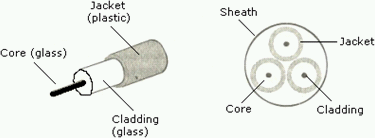
The major advantages offered by optical fiber over wire media (i.e., twisted pair and coaxial cable) are its immunity to noise, less signal distortion and higher bandwidth. Some of the advantages/disadvantages of optical fiber have been discuss below:
Advantages
- Immunity to Electrical Noise
Fiber optics communication uses light signals in place of electrical signals. Instead of electrons that are found in metallic media fiber optics have electrically non-conducting photons, so the light signal is totally immune to the electrical noise.
- Reduced Loss of Signal Strength
Optical fibers have less loss of signal strength. The strength of a light signal is typically reduced only slightly after propagation through several kilometers of optical fiber cables. For regeneration of signals, repeaters can be placed as far as 50-60kms.
- Large Information Carrying Capacity
Optical fiber cables can support much higher bandwidths than wire media and hence offer large information carrying capacity.
- Security
Signals in the cable are secure from unauthorized listeners. It is difficult to tap into the cable as no light escapes out.
Disadvantages
- Cost Factor
The major disadvantage of optical fiber is its high costs. It is very expensive transmission media because of its high manufacturing costs.
- Installation and Maintenance of Cable
Laying of the cable is a complex job and it needs a lot of time and ground work.
- Termination and Connection
Any break or cracking in the core of an optical fiber diffuse light and distorts the signal. Termination and connection of fiber optic cable needs special tools. It is very difficult to support multiple users on the fiber, that is why, fiber optic cable is still used for point to point communication systems.
- Fragility
Optical fiber cable is very fragile. Due to its glass or plastic construction, it can be more easily broken than wires.
Wireless Transmission
Wireless transmission comes under unguided transmission. The need of wireless transmission arises, when it is required to be on-line all the time. For wireless communication, there is no need of using twisted pair, coaxial or optical fiber cables. In this type of transmission, sending and receiving of signals are achieved by means of an antenna. In data communication, at sending end, the antenna radiates electromagnetic energy into the medium and at receiving end; the antenna receives the electromagnetic energy from the surrounding medium. There are basically two types of transmission: directional and omni-directional. In directional transmission, the transmitting antenna puts out a focused electromagnetic beam, so it is very important that the transmitting and receiving antenna must be carefully aligned to each other. In omni-directional transmission, the transmitting antenna spreads out the transmitting signals in all directions that are received by many antennas. Here are list of ways in which wireless transmission is possible:
Radio Transmission
Radio waves are easy to generate, can travel long distances and penetrate (passes) buildings easily. So they are widely used for communication. They are omni-directional, which means that can travel in all directions. The properties of radio waves are frequency dependent. At low frequencies, these waves pass very well through obstacles but he power falls off sharply as the distance increases from source. At high frequencies, radio waves tend to travel in straight lines and bounce off obstacles. They are also absorbed by rain. At all frequencies, radio waves are subject to interference from motor and other electrical equipments. In VLF, LF and MF bands, radio waves follow the ground. These waves can be detected at the lower frequencies for perhaps 1000km less than higher ones. At such frequencies, radio waves easily pass through buildings but the main problem is that under certain atmospheric conditions the signals may bounce several times.
Microwave Transmission
Transmission of waves, above 100 Mhz frequency is known as microwave transmission. Microwave transmission is a directional type of transmission in which multiple transmissions are lined up in a row to communicate with multiple receivers in a row without any interface. Microwave is also relatively in-expensive than the optical fiber. There are two types of microwave transmissions:
- Terrestrial Microwave
Microwaves travel in a straight line and therefore required line of sight transmission. The distance that can be covered by a line of sight signal, depends on the height of the antenna. For 10m high towers, repeaters can be spaced 80km apart. Typically these antennas are mounted on towers.
- Satellite Microwave
Emerging mobile networks encompass a broad spectrum of technologies ranging from analog to digital cellular phones, satellite networks, etc. satellite communication uses microwave frequency antennas to receive radio signals from transmitting stations on earth and to relay the signals back to earth stations. The satellite serves as an electronic relay station. Earth station A transmits signals of a specific frequency (uplink) to the satellite. In turn the satellite receives the signals and retransmits them back to earth station B.
Multiplexing
Combining multiple signals (analog and digital) for transmission over a single line or media is known as multiplexing. A common type of multiplexing combines several low-speed signals for transmission over a single high-speed connection. Multiplexing is used to enable many users to share the system.
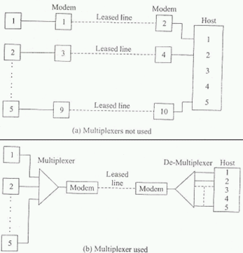
Three types of multiplexing approaches that can be employed are frequency, time and wavelength divisions.
Frequency-Division Multiplexing (FDM)
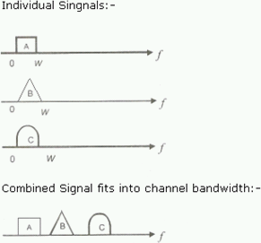
FDM is useful when the bandwidth of the transmission medium is more than the required bandwidth of all the signals to be transmitted. A number of signals can be carried simultaneously, if each signal is modulated onto a different carrier frequency and the carrier frequencies are sufficiently separated such that the bandwidths of the signals do not overlap. FDM was introduced in the telephone network in the 1930s. The basic analog multiplexer combines 12 voice channels in one line. Each voice signal occupies 4 kHz of bandwidth. The multiplexer modulates each voice signal so that it occupies a 4 kHz slot in the band between 60 and 108 kHz. The combined signal is called group.
Time-Division Multiplexing (TDM)
Time division multiplexing provides a user with full channel capacity but divides the channel usage into time slots. Here, the available time is divided into small slots and each of these slots is occupied by one of the signal streams that are to be sent. The slot is assigned to each signal one by one in a round robin manner. Only one signal occupies the channel at one instant. It is thus quite different from FDM, in which all signals are sent at the same time each occupying a different band.

A TDM system is a serial system because the signal from each user follows in time the signal from another user. The overall bandwidth of TDM result exceeds any individual signal. This is because the TDM output carries much more information and information requires bandwidth. The final bandwidth is equivalent to sum of individual bandwidths of all signals.
Wavelength Division Multiplexing (WDM)
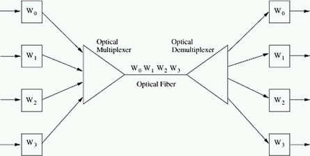
Wavelength Division Multiplexing (WDM) is a technique that multiple signals are carried together as separate wavelengths (color) of light in a multiplexed signal. WDM is used in optical fiber networks. WDM and FDM (Frequency Division multiplex) are both based on the same principles but WDM applies to wavelengths of light in optical fiber while FDM is used in electrical analog transmission. A WDM optical system using a diffraction grating is completely passive, unlike electrical FDM, and thus is highly reliable. Further, a carrier wave of each WDM optical channel is higher than that of an FDM channel by a million times in frequency (THz versus MHz).
Circuit Switching
When we have multiple work stations then a problem is connecting them for one to one communication. One solution for this problem is to establish point to point connection between each individual pair of stations. To interconnect n stations, n(n-1)/2 individual connections are needed. For example, to connect 100 components then totally 4950 individual connections are required. This requirement increases drastically as the number of stations to be increases and for large number stations, it is almost impossible to maintain connections. Now to overcome this problem switching is better solution. The switches can be placed on the transmission path so that the stations do not need to be interconnected directly. Switches are hardware/software capable of creating connections temporally between two or more stations.
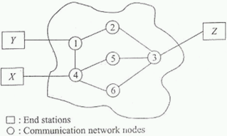
Circuit switching can use either of the following two technologies:
Space Division Switching
It was originally developed for transmitting analog data but it now carries digital data also. In space-division switching, users have a channel dedicated to themselves. Each connection requires the establishment of physical path through the switch that is dedicated solely to the transfer of data between two endpoints. The basic building block of the switch is a metallic cross-point that can be enabled or disabled by a control unit.
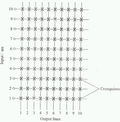
# Multistage Switches
In this different crossbar switches are combined in several stages. Here, devices are linked to switches, which in turn are linked to a hierarchy of other switches. The design of multistage switches depends on the number of stages and the desired number of switches in each stage.
Time Division Switching
Time division switching uses time-division multiplexing to implement switching function. Two methods are used in time-division multiplexing:
- Time-Slot Interchange (TSI)
Time Division Multiplexing (TDM) bus
Note: Continue in Next Part.
HAVE A HAPPY CODING!